
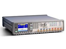
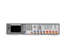
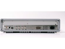


Генератор импульсов, сигналов стандартной/произвольной формы и шума Keysight 81150A
Подробнее
Описание
Импульсный генератор произвольного шума Keysight 81150A с импульсной функцией - это высокоточный генератор импульсов, расширенный за счет универсальных возможностей генерации сигналов, модуляции и искажения, позволяющих максимально нагружать ваше устройство.
Ключевые возможности и технические характеристики
- Генерация импульсов с частотой от 1 мкГц до 120 МГц с изменяемой длительностью фронта/спада
- Генерация сигнала синусоидальной формы с частотой от 1 мкГц до 240 МГц
- Генерация сигналов произвольной формы с разрешением 14 бит и частотой дискретизации 2 Гвыб./с
- Объем памяти для сигналов произвольной формы 512 тыс. точек на канал
- Генерация шума с настраиваемым коэффициентом амплитуды и периодом повторения 26 дней
- AM, ЧM, ЧМн, ФМ и ШИМ модуляция с полосой до 10 МГц
- 1 или 2 канала, связанные или несвязанные
- Дифференциальные выходы
Создание и редактирование сигналов
- Программное обеспечение BenchLink Waveform Builder Pro для создания и редактирования сигналов
Предназначен для создания высококачественных сигналов
- Прецизионный генератор импульсов дополнен возможностями универсального генератора, обеспечивая формирование искаженных сигналов с целью тестирования устройств в предельных режимах
- Генератор кодовых последовательностей для создания идеальных и искаженных последовательностей со скоростью передачи до 120 Мбит/с
- Генератор сигналов стандартной/произвольной формы обеспечивает создание сигналов сложной формы и их модуляцию для использования при тестировании различных устройств
- Генератор шума обеспечивает генерацию случайного и повторяющегося шума с очень длительным периодом повторения, что упрощает идентификацию проблем
Генератор Keysight 81150A может использоваться в самых разных приложениях
- Источник шума для тестирования на физическом уровне систем связи и компьютерных шин, например, MIPI и PCI Express Gen 3
- Генерирование сигналов для тестирования шины FlexRay
- Генерирование сигналов тактовой частоты
- Системный источник сигналов синхронизации
- Тестирование радиолокационных систем
- Тестирование аналого-цифровых устройств
- Проверка целостности сигнала
Характеристики
| Pulse characteristics | |||
| 81150A | |||
|
Frequency range High bandwidth amplifier High voltage amplifier |
1 μHz to 120 MHz 1 μHz to 50 MHz |
||
| Frequency resolution | 1 μHz | ||
|
Pulse width Range High bandwidth amplifier High voltage amplifier Resolution Accuracy |
4.1 ns to (period - 4.1 ns) typ. 10 ns to (period - 10 ns) 100 ps, 6 digits ± 500 ps ± 50 ppm |
||
|
Transition time (independent rise and fall) Range High bandwidth amplifier High voltage amplifier Resolution Accuracy High bandwidth amplifier High voltage amplifier |
2.5 ns to 1000 s (10% to 90%) 7.5 ns to 1000 s (10% to 90%) 100 ps, 6 digits ± 500 ps ± 50 ppm -1000 ps to +500 ps ± 50 ppm |
||
| Overshoot | 2% typ.1 | ||
| 1. Overshoot disappears for transitions times > 5 ns (high bandwidth amplifier) and > 15 ns (high voltage amplifier). | |||
| 2. Overshoot disappears for transition times > 2 ns. | |||
| Sine characteristics | |||
| 81150A | |||
|
Frequency range High bandwidth amplifier High voltage amplifier |
1 μHz to 240 MHz 1 μHz to 50 MHz |
||
| Frequency resolution | 1 μHz | ||
| Harmonic distortion (High bandwidth amplifier 50 Ω into 50 Ω) |
1 μHz to 2 MHz 2 MHz to 10 MHz 10 MHz to 35 MHz 35 MHz to 70 MHz 70 MHz to 240 MHz |
1 VPP < -62 dBc spec. < -57 dBc spec. < -45 dBc spec. < -35 dBc spec. < -22 dBc spec. |
3 VPP < -62 dBc spec. < -52 dBc spec. < -40 dBc spec. < -30 dBc spec. < -17 dBc spec. |
| Harmonic distortion (High voltage amplifier 50 Ω into 50 Ω) |
1 μHz to 8 MHz 8 MHz to 50 MHz |
10 VPP < -40 dBc < -25 dBc |
|
| Non-harmonic (spurious) distortion |
1 μHz to 20 MHz 20 MHz to 200 MHz 200 MHz to 240 MHz |
-60 dBc typ. -55 dBc typ. -50 dBc typ. |
|
|
SSB phase noise (10 kHz offset) 1 MHz 10 MHz 100 MHz 240 MHz 500 MHz |
-119 dBc/Hz typ. -115 dBc/Hz typ. — -93 dBc/Hz typ. — |
||
| Square characteristics | |||
| 81150A | |||
|
Frequency range High bandwidth amplifier High voltage amplifier |
1 μHz to 120 MHz 1 μHz to 50 MHz |
||
| Frequency resolution | 1 μHz | ||
|
Duty cycle High bandwidth amplifier High voltage amplifier |
(Freq/240 MHz) to 1 – (Freq/240 MHz) e.g. 60 MHz; 25% to 75% (Freq/100 MHz) to 1 – (Freq/100 MHz) e.g. 1 MHz 1% to 99% |
||
| Resolution | 0,1% | ||
| Transition time (10% to 90%) High bandwidth amplifier High voltage amplifier | 2.5 ns typ. fixed 6 ns typ. fixed | ||
| Overshoot | 2% typ. | ||
| Ramp characteristics | |||
| 81150A | |||
| Frequency range | 1 μHz to 5 MHz | ||
| Frequency resolution | 1 μHz | ||
| Linearity | < 0.1% (f < 10 kHz) | ||
| Symmetry | 0.0% to 100% | ||
| Noise characteristics | |||
| 81150A | |||
|
Bandwidth High bandwidth amplifier High voltage amplifier |
120 MHz typ. 40 MHz typ. |
||
| Amplitude distribution | Selectable Gaussian, user defined | ||
| Crest factor (peak/RMS) selectable | 3.1, 4.8, 6.0, 7.0 typ. (Gaussian distribution) | ||
| Noise type | Deterministic, triggerable | ||
| Repetition time | ~ 26 days | ||
| Arbitrary characteristics | |||
| 81150A | |||
| DAC sample rate | 2 GSa/s1, fixed | ||
| Waveform length | 2 to 512 k points | ||
| Wavelength vs. memory access rate |
2 to 512 k points at memory access rate 1,000 MSa/s1 |
||
| DAC resolution | 14 bits | ||
| Frequency range | 1 μHz to 120 MHz | ||
| Frequency resolution | 1 μHz | ||
| Transition time (10% to 90%) High bandwidth amplifier High voltage amplifier | 1.7 ns typ. 5 ns typ. | ||
|
Filter bandwidth High bandwidth amplifier High voltage amplifier |
240 MHz typ. 80 MHz typ. |
||
| PP jitter | 1 ns typ. | ||
| 1. One step linear interpolation between two memory samples. DAC clock rate is 2,000 MSa/s. | |||
| 2. Three steps linear interpolation between two memory samples. DAC clock rate is 2,500 MSa/s. | |||
| 3. One step linear interpolation between two memory samples. DAC clock rate is 2,500 MSa/s | |||
| Advanced Modes | Three advanced modes exist: | ||
| – Modulation: selects the modulation type: AM, FM, PM, FSK, PWM | |||
| – Sweep: for frequency sweeps | |||
| – Bursts: repeats selected waveform n times | |||
| Modulation | |||
| A modulation input (for AM, FM, PM, FSK, PWM) for each channel is provided on the | |||
| back-panel. In the two-channel instrument one channel can also modulate the other channel. | |||
| Modulation In 1/modulation In 2 | |||
| 81150A | |||
| Input range (full scale) | Selectable ± 2.5 V or ± 5 V | ||
| Frequency range | DC to 10 MHz | ||
| Input impedance | Selectable 10 kΩ, 50 Ω nom. | ||
| Connector | BNC, back panel | ||
| AM | |||
| 81150A | |||
| Carrier waveforms | Sine, square, ramp, arbitrary | ||
| Internal modulation | Sine, square, ramp (up, 50%, down), noise, arbitrary | ||
|
Modulation frequency Internal |
1 mHz to 10 MHz | ||
| External | DC to 10 MHz | ||
| Depth | 0% to 120% | ||
| Double-sideband suppressed carrier | Selectable on/off | ||
| Source | Internal, external, channel | ||
| FM | |||
| 81150A | |||
| Carrier waveforms | Sine, square, ramp, arbitrary | ||
| Internal modulation | Sine, square, ramp (up, 50%, down), noise, arbitrary | ||
|
Modulation frequency Internal External |
1 mHz to 10 MHz DC to 10 MHz | ||
| Deviation range | 1 μHz to 240 MHz1 | ||
| Source | Internal, external, channel | ||
| PM | |||
| 81150A | |||
| Carrier waveforms | Sine, square, ramp, arbitrary | ||
| Internal modulation | Sine, square, ramp (up, 50%, down), noise, arbitrary | ||
|
Modulation frequency Internal External |
1 mHz to 10 MHz DC to 10 MHz | ||
| Deviation range | 0 to 360˚ | ||
| Source | Internal, external, channel | ||
| 1. Max frequency depends on selected waveform. | |||
| FSK | |||
| 81150A | |||
| Carrier waveforms | Sine, square, ramp, arbitrary | ||
| Internal modulation | 50% square | ||
|
FSK rate Internal External |
1 mHz to 50 MHz 1 mHz to 10 MHz |
||
| Frequency range | 1 mHz to 240 MHz1, 2 | ||
| Source | Internal, external, channel | ||
| 1. Max frequency depends on selected waveform. | |||
| 2. For export control: Effective switching time is 40 ns. | |||
| PWM | |||
| 81150A | |||
| Carrier waveform | Pulse | ||
| Internal modulation | Sine, square, ramp (up, 50%, down), noise, arbitrary | ||
| Modulation frequency Internal External | 1 mHz to 10 MHz DC to 10 MHz | ||
| Deviation range | 0% to 100% of pulse width | ||
| Source | Internal, external, channel | ||
| Sweep An independent frequency sweep is provided for each channel. | |||
| 81150A | |||
| Waveforms | Pulse, sine, square, ramp, triangle, arbitrary | ||
| Type | Linear or logarithmic | ||
| Direction | Up or down | ||
| Sweep time | 100 μs to 500 s | ||
| Start frequency/stop frequency | 1 μs to 240 MHz3 | ||
| Amplitude flatness (relative to 1 kHz, 2 VPP) | — | ||
| Trigger source | External, internal, manual | ||
| Marker | Frequency marker | ||
| 3. Max frequency depends on selected waveform. | |||
| Burst An independent burst capability is provided for each channel. | |||
| 81150A | |||
| Waveforms | Pulse, sine, square, ramp, triangle, arbitrary | ||
| Frequency | 1 μHz to 120 MHz | ||
| Modes | Externally triggered, internally triggered, externally gated | ||
| # of waveforms in a burst | 2 to 231 - 1 (~ 2 billion) | ||
| Trigger period | 16.7 ns to 9999 s | ||
| Start phase4 | –360 to +360˚ | ||
| Gate source | External | ||
| Trigger source | External, internal, manual | ||
| 4. Available for all waveforms except pulse, square and ramp. | |||
| Outputs | |||
| Main outputs A selectable single-ended or differential output is provided for each channel on the front-panel. | |||
| Max. frequency | |||
| 81150A | |||
| High bandwidth amplifier | 120 MHz pulse/240 MHz sine | ||
| High voltage amplifier | 50 MHz | ||
| Out 1/Out 2 | |||
| 81150A | |||
| Output type | Single-ended or differential | ||
|
Amplitude (50 Ω into 50 Ω) High bandwidth amplifier 1 μHz to 120 MHz 120 MHz to 240 MHz 1 µHz to 330 MHz 330 MHz to 500 MHz High voltage amplifier 1 μHz to 50 MHz |
50 mVPP to 5 VPP1 typ. 50 mVPP to 3VPP1 typ. 100 mVPP to 10 VPP1 typ. |
||
|
Amplitude (50 Ω into open, 5 Ω into 50 Ω) High bandwidth amplifier 1 μHz to 120 MHz 120 MHz to 240 MHz 1 µHz to 60 MHz High voltage amplifier 1 μHz to 50 MHz |
100 mVPP to 10 VPP1 (to 9 VPP2) typ. 100 mVPP to 5 VPP1 typ. 200 mVPP to 20 VPP1 typ. |
||
| DC amplitude accuracy | ± (1.5% of setting + 5 mV) | ||
| Voltage window (50 Ω into 50 Ω) High bandwidth amplifier High voltage amplifier |
–5 V to +5 V typ. –10 V to +10 V typ. |
||
|
Voltage window (50 Ω into open, 5 Ω into 50 Ω) High bandwidth amplifier High voltage amplifier |
–10 V to +10 V1 (-9 V to +9 V2) typ. –20 V to +20 V typ. |
||
|
DC offset accuracy ± 5 V voltage window ± 10 V voltage window ± 20 V voltage window |
± (25 mV + 1%) ± (50 mV + 1%) ± (75 mV + 1%) |
||
| Resolution | 1 mV, 4 digits | ||
| Output impedance | Selectable 50 Ω / 5 Ω typ. | ||
| Variable load impedance | 0.3 Ω to 1 MΩ3 | ||
| Protection | Short-circuit protected, overload disables main output | ||
| Connector | BNC, front panel | ||
| 1. All amplitudes are single-ended amplitudes. Differential peak-peak amplitudes are twice the single-ended value. | |||
| 2. 10 VPP for 50 Ω into open; 9 VPP for 5 Ω into 50 Ω. | |||
| 3. Current of normal Out plus current of complement Out is limited to 440 mA per channel. | |||
| 4. Only for 50 Ω into open. | |||
| External reference input | |||
| 81150A | |||
| Lock range | 10 MHz ± 500 ppm | ||
| Input level | 200 mVpp to 5 Vpp | ||
| Impedance | 1 kΩ nom., AC coupled | ||
| Connector | BNC, rear panel | ||
| Internal frequency characteristics | |||
| 81150A | |||
| Accuracy | ± 50 ppm | ||
| Stabilty | ± 2 ppm, 0 to 50 ºC | ||
| Aging | ± 1 ppm per year | ||
| External Input | |||
| A common external input is provided for both channels on the front panel. The external input is used for external trigger or external gate modes. | |||
| 81150A | |||
| Frequency range | DC to 120 MHz | ||
| Input range | –10 V to +10 V | ||
| Maximum input amplitude | 10 VPP | ||
| Input sensitivity | 200 mVPP | ||
| Threshold | |||
| Range | –10 V to 10 V | ||
| Resolution | 100 mV | ||
| Impedance | Selectable 10 kΩ/50 Ω, DC coupled | ||
| Slope | Selectable, rising/falling/both | ||
| Pulse width | > 3.3 ns | ||
| Transition time | < 100 ns | ||
| Connector | BNC, front panel | ||
| Frequency counter | The frequency applied to external input is measured | ||
| General Specifications | |||
| 81150A | |||
| Power supply |
100 V to 240 V ~, 50 to 60 Hz 100 V to 127 V ~, 50 to 400 Hz |
||
| Power consumption | 110 W nom. | ||
| Operating temperature | 0 to 50 ºC | ||
| Operating altitude | Up to 2000 m | ||
| Storage temp. | –40 to 70 °C | ||
| Stored states | 4 named user configurations and factory default | ||
| Power on state | Default or last state | ||
| Interface |
2 x USB 2.0 standard A, 1 x USB 2.0 standard B, GPIB and LAN |
||
| Programming language |
SCPI-1997 IEEE-488.2 LXI compliant to LXI class C (rev. 1.1) |
||
|
Dimensions (WxHxD) Bench top Rack mount |
439 mm x 108 mm x 456 mm 428 mm x 89 mm x 439 mm |
||
| Weight | 8 kg | ||
| Safety designed to |
IEC61010-1 UL61010 CSA22.2 61010.1 certified |
||
| EMC tested to | IEC61326 | ||
| Warm up time | 30 min. | ||
| Calibration interval | 2 years recommended | ||
| Cooling requirements | When operating the instrument choose a location that provides at least 80 mm of clearance at rear, and at least 30mm of clearance at each side | ||
| Definitions | |||
| Specification (spec.) | The warranted performance of a calibrated instrument that has been stored for a minimum of 2 hours within the operating temperature range of 0 °C to 55 °C and after a 45-minute warm up period. Within ± 10 °C after autocal. All specifications include measurement uncertainty and were created in compliance with ISO-17025 and Z540 methods. Data published in this document are specifications (spec.) only where specifically indicated. | ||
| Typical (typ.) | The characteristic performance, which 80% or more of manufactured instruments will meet. This data is not warranted, does not include measurement uncertainty, and is valid only at room temperature (approximately 23 °C). | ||
| Nominal (nom.) | The mean or average characteristic performance, or the value of an attribute that is determined by design such as a connector type, physical dimension, or operating speed. This data is not warranted and is measured at room temperature (approximately 23 °C). | ||
| Measured (meas.) | An attribute measured during development for purposes of communicating the expected performance. This data is not warranted and is measured at room temperature (approximately 23 °C). | ||
| Accuracy | Represents the traceable accuracy of a specified parameter. Includes measurement error and timebase error, and calibration source uncertainty. | ||
Документы
Описание
| Опции | Описание |
| 81150A-001 | One output channel for 81150A |
| 81150A-002 | Two output channels for 81150A |
| 81150A-1A7 | Calibration + Uncertainties + Guardbanding (Not Accredited) |
| 81150A-DOC | Documentation |
| 81150A-PAT | Pattern Generator License for 81150A |
| 81150A-SCD | Standard Calibration Document |
| 81150A-Z54 | Z540.3 Calibration Documents |
| 81110A-1CP | Rackmount and handle kit |
| 81134A-PLG | Continental European power cord - ONLY FOR EU DISTR W MULT PWR CORD STANDARDS |
| N6171A | MATLAB Software |
| N6171A-M01 | MATLAB-Basic Package, individual license - node-locked |
| N6171A-M02 | MATLAB-Standard Package, individual license - node-locked |
| N6171A-M03 | MATLAB-Advanced Package, individual license - node-locked |
| R-50C-011-3 | Calibration Assurance Plan - Return to Keysight - 3 years |
| R-50C-011-5 | Calibration Assurance Plan - Return to Keysight - 5 years |
| R-50C-016-3 | Keysight Calibration + Uncertainties + Guardbanding - 3 years |
| R-50C-016-5 | Keysight Calibration + Uncertainties + Guardbanding - 5 years |
| R-50C-066-3 | Poverka Service - 3 Years (for use in Russia only) |
| R-50C-066-5 | Poverka Service - 5 Years (for use in Russia only) |
| R-51B-001-3C | Warranty Assurance Plan - Return to Keysight - 3 years |
| R-51B-001-5C | Warranty Assurance Plan - Return to Keysight - 5 years |
Модели
| Модели | Описание |
| 81150A | Генератор импульсов, сигналов стандартной/произвольной формы и шума |
